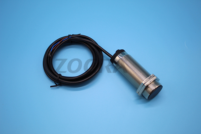
86-0577-21019000


Power supply: 220VAC + / - 15%
Load current: less than or equal to 5A
Insulation resistance: > 500 m Ω
Output signal: switch signal
Ambient temperature: - 20 ℃ ~ 60 ℃
Environmental humidity: less than 90%
Installation dimensions: Φ 38 x 105 mm
Weight: 0.5 KG
Protection grade: IP66
Detection speed range: 1-220 revolutions/min
Tripping time: 3-18 seconds
Response time: < 2mS
Detection spacing H2: less than or equal to 8mm
Minimum safe working distance H1: greater than 20mm
Working principle:
Playing slide switch is different from the proximity switch inside the main difference is that a delay circuit, he can be adjusted according to the different speed of driven shaft internal delay card die blocked to protect equipment, rotary detectors installed on the driven shaft such as sketch it is through the test piece on the drive shaft, by using the principle of electromagnetic induction to speed switch pulse signal (when detecting that rotational speed switch from 4 to 8 mm distance for a pulse), in one, for example:Current instantaneous speed switch through a string of relay relay and delay to set the number of seconds, equipment need to the driven shaft rotational speed switch two pulse, if the speed switch is set in 8 seconds, equipment turn a circle is less than 8 seconds, speed switch through a series of relay action (and relay), when the device turning a circle than 8 seconds, speed switch that has jammed locked-rotor, through a series of relay to make the machine (power relay), protection equipment
Product features:
1. Non-contact, no moving parts, no wear, long safety life, low maintenance cost, suitable for site with harsh environment.
2. Integrated structure, no setting, debugging and simple installation.
3. Small size, light weight and long life
4. Load short circuit protection function -- the rotation detector will not be damaged if it is connected directly to the power supply by mistake.5. The output signal can be used for interlocking with the field equipment or delivered to the DCS control system
6. Status indicator light is provided.When the equipment is in normal operation, the indicator light "flashes";When stop, the indicator light is "on".
7. The time of tripping can be adjusted to 3-18s
Installation instructions:
All transmission devices, such as screw conveyor, hoist, belt conveyor, zipper machine, crusher, etc. should be installed at the transmission shaft (the end of the machine), as shown below.Note: the installation position of the rotating speed monitor in the installation diagram depends on the specific situation, and it is not necessary to stick to this diagram. On the premise that normal operation is not affected, only the condition of "evenly spaced pulse signals per unit time" can be satisfied.
Mechanical installation process:
1, remove the end cover, acuity Φ 12 holes in the center of the end cover, drill in the lower end cover Φ 5. L hole, tapping M6 (with rotating speed monitor support two holes matching processing) after screwed cover and stand
2, on shaft head Φ 5.1 holes, tapping M6, 10 ~ 15 mm deep
3. Tighten the two-headed screw
4. Install end cover
5. Install test plate, F is more than 20mm and fix with nut
6. Install rotation speed monitor and adjust G=4mm
Some machines have long drive shafts that extend beyond the end cover. For this situation, the test piece can be made into a circle and fixed on the shaft head (please note that the plane of the test piece is parallel to the probe plane of the rotation speed monitor.If mounted on a metal base, please pay special attention to the distance of F to prevent the equipment from starting due to the strong interference of magnetic materials.
Electrical wiring: this product and intermediate relay are used in series (see electrical wiring diagram above).Intermediate relay coil withstand voltage 220V.
Test sheet: plain sheet iron, 2 blades, 100 x 10 x 2mm.
Reference formula for tripping time: T (tripping time) > [60s x 3 (constant value)]
Matters needing attention:
1. If it is installed on the metal base, please pay special attention to the distance to prevent the equipment from starting due to strong interference of magnetic materials.
2. The installation distance should be about 4mm to prevent change of G caused by external reasons.
3, equipped with the intermediate relay and mid-december - SD - concatenated Ⅳ speed switch.The two normally open contacts of the intermediate relay are connected in parallel to increase the current capacity.
4. If the auxiliary rotation axis is slow, the time of tripping can be increased.
5. It is strictly prohibited to connect the power supply directly with the unconnected relay. If the product is damaged due to the direct connection of power supply, it is "man-made damage", which is not covered by the free warranty.
6, outdoor installation mid-december - SD - Ⅳ speed switch installation cover as much as possible, can prolong the service life of the product.